Guides
Guides Nicola FeliceOur guides are designed to give an idea of the possibilities offered by the technical solutions and the materials that we are able to supply.
Guides are currently are available about the different types of materials and styles of finishes, both for prototypes and pre-series production.
Guide to materials
Guide to materials Nicola FeliceThe development of additive manufacturing has made available to designers and users a variety of materials in which it is often difficult to navigate.
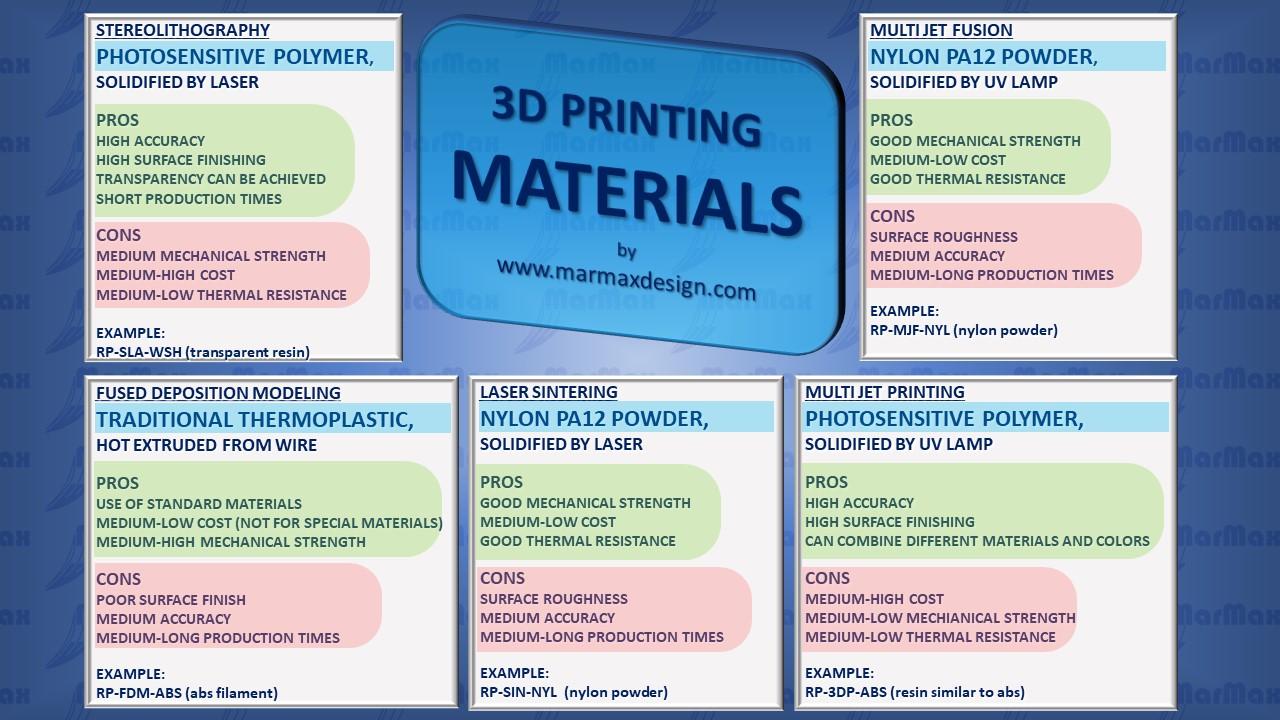
Let's try to shed some light with the help of this diagram, which focuses on the most used materials in various technologies: photosensitive polymers in stereolithography and multi-jet printing, nylon powder in sintering and multi-jet casting, the traditional thermoplastic in wire extrusion.
The following table summarizes the characteristics of the most used materials in 3D printing. The green color indicates a good level of the indicated property, the gray color indicates that the material is not very suitable or does not possess the indicated characteristic, the yellow color represents an intermediate situation (acceptable, not excellent). Obviously the table is not exhaustive of all the materials, but is intended to guide the choice, according to the most relevant needs of the user.

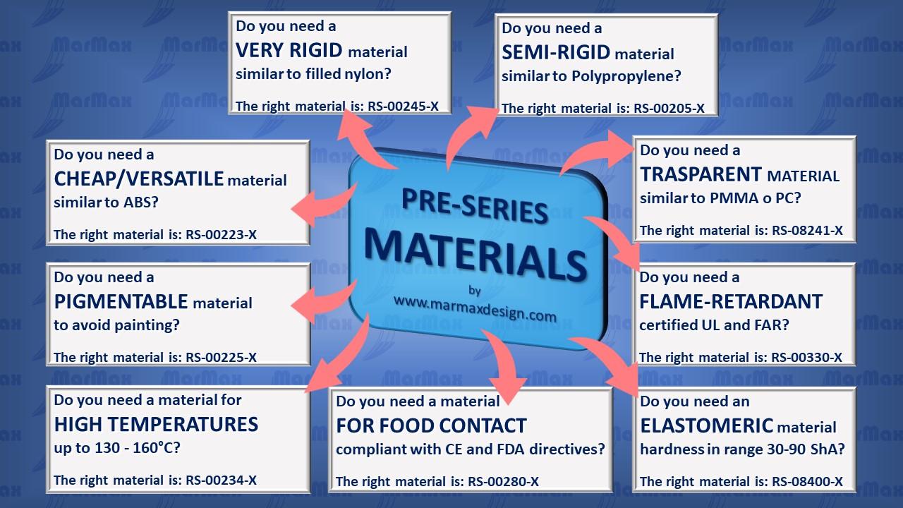
Moving from 3D printing to vacuum casting, we are again faced with a wide range of materials, which can be used for pre-series production. In this case the constructive solution is the same for all, it is the vacuum casting of bi-component polyurethane in a silicone mold. The wide range of formulations available for polyurethanes makes it possible to satisfy the most varied needs, which we have tried to summarize in this diagram.
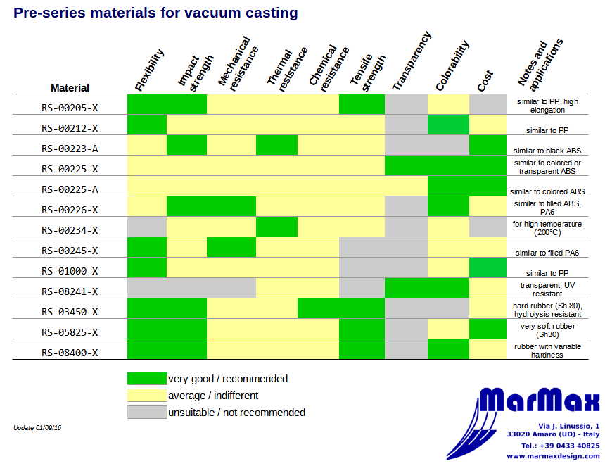
The following table summarizes the characteristics of the materials available for the vacuum casting of pre-series, highlighting merits and demerits of the various materials, with the color legend already illustrated above: green for good characteristics of the indicated property, grey if the material is not very suitable or does not possess the indicated property, yellow for an intermediate situation.
The detailed technical data sheets of the materials mentioned in these tables are available in the datasheet section of our website.
For an easy consultation on other media, this guide is also available in PDF format:
Stereolithography finishes
Stereolithography finishes Martina FelicePrototypes made in stereolithography can be finished in various ways, from basic finishing to RAL varnishing. Usually, the finishing is done only on the aesthetic side, unless otherwise agreed and with the exception of the transparent effect that requires finishing on both sides.
FB - Basic finishing

This type of finishing is the basic finish directly derived from the machine, without further processing, except those strictly necessary to separate the object from the support platform. Surface quality depends heavily on machine positioning that can highlight or hide process stratification.
FS - Standard finishing

This is the most common finish, consisting in sanding and sandblasting the piece, which thus assumes a translucent white appearance.
FT - Transparent finishing

With the Watershed 1122XC material, it is possible to obtain a transparent glass-like finish. This is possible by sanding, polishing and painting the workpiece on both sides, compatibly with the geometry of the part.
FM - Metal finishing

In this case, the prototype, after being polished, is subjected to vacuum metallization. The final surface is glossy and has a highly reflective power, but may have slight cracking, which may also occur over time, due to the different dilatations that characterize the resin and the metal.
FP - Painted finishing

This type of finish is obtained by painting the model with a color you choose, glossy or opaque (RAL or Pantone shades are possible). In this way you can also get opaque metal-like finishes.
Vacuum casting finishes
Vacuum casting finishes Martina FeliceWith silicone molds you can get a good variety of finishes, as explained below. All described effects (except metallic ones) can be applied on a pigmented support or on a transparent base (colorless or colored). Unless otherwise agreed, the finish is only made on the aesthetic side. Exceptions are transparent pieces, which are nevertheless finished on both sides.
FLL - Glossy smooth finish

This type of finish is obtained by polishing as much as possible the master prototype. The pieces thus obtained have a glossy finish and, if the material is transparent, the effect is similar to glass. Caution: this finish is hard to get and very time consuming moreover, defects and scratches are very noticeable on the parts thus finished.
FLO - Smooth matt finish

This finish, characterized by a smooth but non-glossy surface, is one of the most used and versatile finishes, easily available on almost all geometries. If the casting material is transparent, the effect is that of mildly acidified glass.
FGL - Slightly rough finish

The FGL surface has a light roughness on it, which can have aesthetic purpose, but can also help hiding any irregularities that may occur in most complex prototypes. Also this is a very used and versatile finish. On transparent material, the effect is similar to sandblasted glass.
FGG - Very rough finish

In this finish the texture is more evident. In some cases, high surface roughness can make defect correction difficult and can also reduce the mold life.
FST - Structured Finish

A very special finish, characterized by a high roughness, which simulates a fibrous material. It greatly reduces die life.
FML - Polished metallic finish

This type of finishing is achieved by vacuum-vaporizing metal. The coating is a few microns and therefore has aesthetic and non-structural purposes. The vacuum metallization procedure increases production times.
FMS - Finitura metallizzata satinata

This type of finish is obtained by painting the parts with a matte metallic paint. Execution time and cost are lower than for vacuum metallization, but with this method you can not get the glossy effect.
Transparent models
Transparent models Martina Felice3D printing and small series of transparent models
This guide is intended to help you understand how transparent models can be obtained from 3D printing and vacuum casting and, starting from the definition of the concept of transparency, provides indications on the possibilities and limits of these two solutions.
What is transparency?
When we say "transparent" we are all pretty sure of what we mean, but there are aspects of the concept of transparency that are worth investigating, to better understand what you can expect when you want to get a transparent prototype from 3D printing.
Transparency is the capability of a body to allow the passage of light and therefore the vision of objects located beyond it.
This capability is determined by two factors:
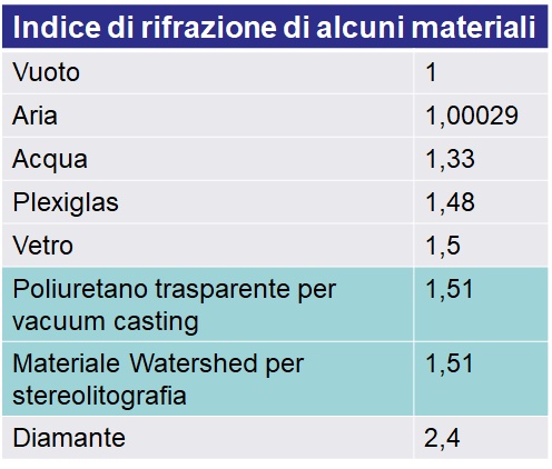
- by the material of which the object is made, i.e. by its index of refraction: for example, having conventionally set the index of refraction of the vacuum to 1, the air is indexed 1.00029, the water 1.33, the glass about 1.5, the diamond 2.4;
- by the surface of the object: if the surface is rough, the actual incidence angle of light is not what you see macroscopically but varies from point to point because the various light rays hit the microscopic facets of the roughness, each characterized by a normal, with an overall effect of reflection and diffusion or alteration of the path of the light rays, which reduces the actual transparency.
As a consequence, to obtain a transparent prototype it is necessary:
- to use a material with a good index of refraction, i.e. what we would call a transparent material;
- to have a surface as shiny as possible and free of macroscopic or microscopic geometric discontinuities.
How to get transparent models?
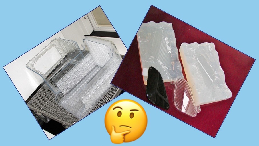
In the field of prototypes, the two ways to obtain this kind of result are stereolithography and vacuum casting.
In the case of stereolithography, it is necessary to use a transparent material such as Somos Watershed 11122XC and then proceed to finish the surface of the product until it is smooth and shiny. In most cases the object is then painted with transparent varnish to enhance the final effect.
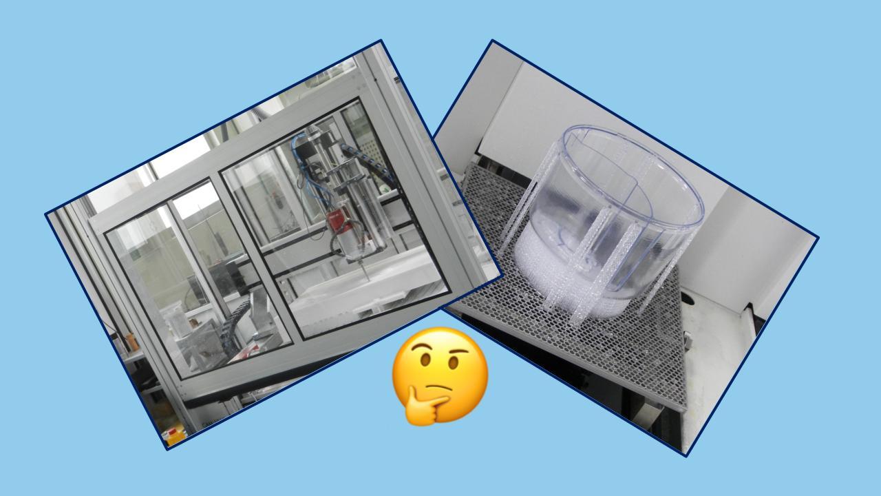
The second path that can be followed to obtain a transparent model is to cast a transparent polyurethane inside a silicone mold. In this case, to ensure the transparency of the casted object, it is necessary that the master used to fabricate the mold, usually made by stereolithography, is perfectly polished and reflective, i.e. with the surface characteristics, and related problems, described in the previous paragraph.
Generally, it is worth following the first road when you want to make a single prototype and you want to contain costs, it makes sense to follow the second way if you want to make a small series of models and you are looking for more performing materials (in terms of mechanical strength and aesthetic quality).
Technical transparency or aesthetic transparency?
In both solutions described above, the methods required to polish the models involve a cost and, more importantly, they are not always possible. In general, in order to polish and paint an object, it is necessary that all its surfaces, internal and external, are accessible to finishing tools (usually manual tools) and to the paint that normally is airbrushed. If this is not possible, the transparency of the object will be somewhat reduced. This problem, however, is in many cases less restrictive than it may appear. To better understand the situation we should refer to the distinction that is made, in practice, between aesthetic transparency and technical transparency.
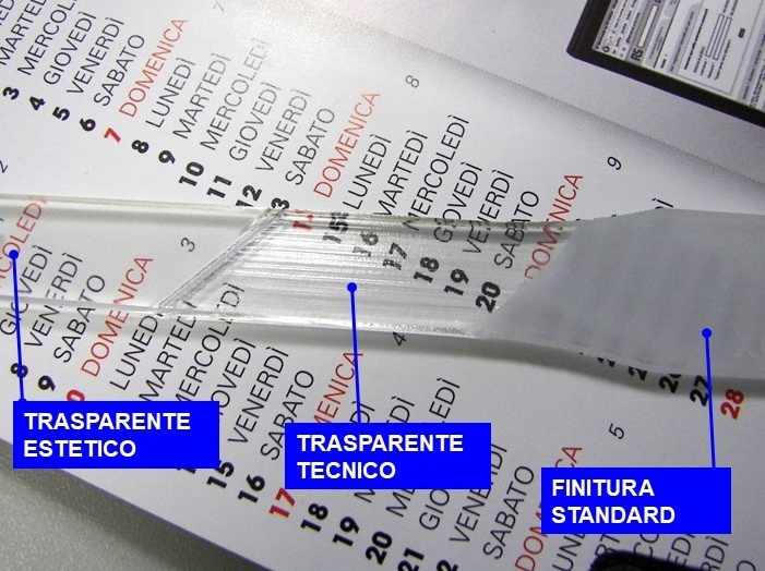
The aesthetic transparency is the "glass type appearance" that we can expect for example from a lamp or from a refrigerator showcase: a transparency that allows us not only to see through without any attenuation or deformation, but also to appreciate the smooth and glossy finish of the surface.
The technical transparency is instead what we can ask for a pipe fitting, where we want to see the liquid flow, or for a box that is designed to contain electronic parts: in this cases, it is important to see through the surface, but its aesthetic appearance is much less important because the defects are not relevant or are easily confused with the other elements that make up the assembly. In this case, even if you can not polish and paint all surfaces perfectly, often the final transparency effect is quite acceptable also because it is important to keep in mind that any geometric discontinuity (edges, ribs, holes, turrets, etc.) determines a reduction in transparency.
In conclusion, when you want to create a transparent prototype it is important to decide what the real needs are because the so-called "technical transparency", in not only easier and faster to obtain, but also less expensive.
For an easy consultation on other media, this guide is also available in PDF format:
Would you like to know more?
If you have any doubts about whether to choose the stereolithography solution instead of silicone molds, or you want to better understand if you need aesthetic or technical transparency, do not hesitate to contact us!
CNC milling VS 3D printing
CNC milling VS 3D printing Nicola FeliceIn this guide we try to illustrate the characteristics, advantages and disadvantages, both from a technical and economic point of view, of the two solutions most used today to translate a project or an idea into reality.
Milling
In general terms, milling is a process in which, starting from a solid, which can have the shape of a block, plate, bar, material is removed by means of a cutting tool.
This general concept is translated into a very wide variety of machines, which differ in size, solidity, precision, operating principle. In particular, some machines operate by moving the tool in the direction of the cut, while the piece remains fixed, others move the piece, while the structure that carries the tool remains fixed. Furthermore, depending on the characteristics of the machine, these movements can be characterized by 3 or 4 or 5 degrees of freedom, thus determining the complexity of the geometries that can be created.
Milling is then often associated with turning which also operates by removing material using a cutting tool, but whose application is limited to the realization of axial-symmetrical pieces.
3D printing
3D printing is a decidedly more recent production solution, which began its development during the last decades of the 1900s and is now consolidated and entered into common use.
The operating principle is opposite to milling and consists in the addition of material which takes place layer by layer, based on the two-dimensional geometry obtained from the succession of sections of the 3D CAD model. The material can be found in both solid and liquid state, and in the form of dust; depending on the type of material, the technical solution adopted to produce the solid object gives rise to a wide variety of technologies and machines, such as sintering, stereolithography, filament extrusion, lamination, jet printing.
Factors to evaluate
Despite the huge variety of machinery and technological solutions available today in both milling and 3D printing, which makes it difficult to establish in general which solution is optimal for the specific problem, it is still possible to identify guidelines to better orientate in the choice process. Let's see together some parameters to keep in mind.
Form
The salient feature of all 3D printing solutions is that of proceeding layer by layer, thus overcoming many undercut problems related to the realization of complex geometries through a solid tool that must move on the piece or inside the piece. Complicated geometric shapes are therefore certainly achievable with greater ease through 3D printing.
Volume
Precisely because of the opposite principle of operation in terms of material subtraction or addition, it is clear that milling will be cheaper for very large pieces because they will have little material to remove (ie similar to solid blocks), while 3D printing will be more efficient for pieces of limited volume for the same size (ie similar to empty boxes).
Dimension
In both sectors there are machines capable of operating on very variable dimensions, therefore the size is not usually decisive in the choice. It should be borne in mind, however, that, when it comes to very large or very small dimensions, the great tradition of the milling sector is often able to offer more efficient solutions in these extreme areas of application.
Precision
In general, it can be said that high precision milling is certainly more precise than even very detailed 3D printing. This does not mean that a certain 3D printing machine cannot perform a piece guaranteeing repeatability and precision higher than a certain milling machine. It should also be borne in mind that in some processes characterized for example by undercuts, some geometries cannot be achieved by milling, and in these cases, the comparison is decidedly in favor of 3D printing. Furthermore, the minimum detail achievable by milling is given by the diameter of the tool that removes the chip, while in the case of 3D printing the limit is given by the diameter of the element that brings the material (which can be an extruder, a laser, the nozzle of a printer, etc.); it is therefore likely that in the case of milling the lower dimensional limits are more critical for negative details, while for 3D printing the positive details will be more critical.
Material
Today it is possible to mill practically any material of technical interest, while the materials available with 3D printing are more limited even if the availability increases constantly and has already covered almost all the most relevant materials in the plastic and metal sector. It is also essential to keep in mind the fact that the functional characteristics of a material are not determined only by its chemical composition, but also by its internal structure which is determined by the production technology. For example, the mechanical strength characteristics that can be expected from a lever made by milling a nylon block, are absolutely higher than those obtainable by filament extrusion of the same material and, usually the characteristics of the milled pieces are isotropic, while instead 3d printing is an anisotropic process which will therefore give rise to pieces that can have very different characteristics in different directions. So, when the characteristics of the material are fundamental for the application being designed, often the choice must fall on the milling.
Quantity
Actually, neither 3D printing nor milling are very suitable solutions for producing large series, where forming and stamping techniques are best applied. For medium print runs, in general it can be said that for small pieces the geometric complexity factor usually prevails and therefore it makes sense to move towards 3D printing, while for large pieces the volume factor prevails and therefore milling is more economical. If, on the other hand, it is a single piece or with a run of very few pieces, it is advisable to take into consideration the pre-process factor which, in general, is more expensive and time-consuming with milling, as it requires the development of a CAM program for the generation of a tool path and a machine tooling/setting job, which can significantly affect costs, especially for making single or very few pieces.
Times
In general, 3D printing is faster than milling, both in the process itself, and in the work that is required as support, since the generation of the tool path and the machine tooling in 3D printing are standardized and rapid processes.
Costs
Given the variety of solutions available in both processes, it is difficult to say a priori which one is economically more convenient. In general, it should be borne in mind that the areas in which 3D printing works best are those characterized by complex geometries and low volume/size ratio, and in these sectors it will be likely to obtain lower costs using 3D printing, while it will probably be cheaper to produce in milling simple parts characterized by a high volume/size ratio.
Conclusions
Wanting to identify general guidelines, it can be said that 3D printing is faster than milling and works better for thin and geometrically complex pieces, while milling is more effective for simple and stocky pieces and has greater flexibility in the choice of materials.
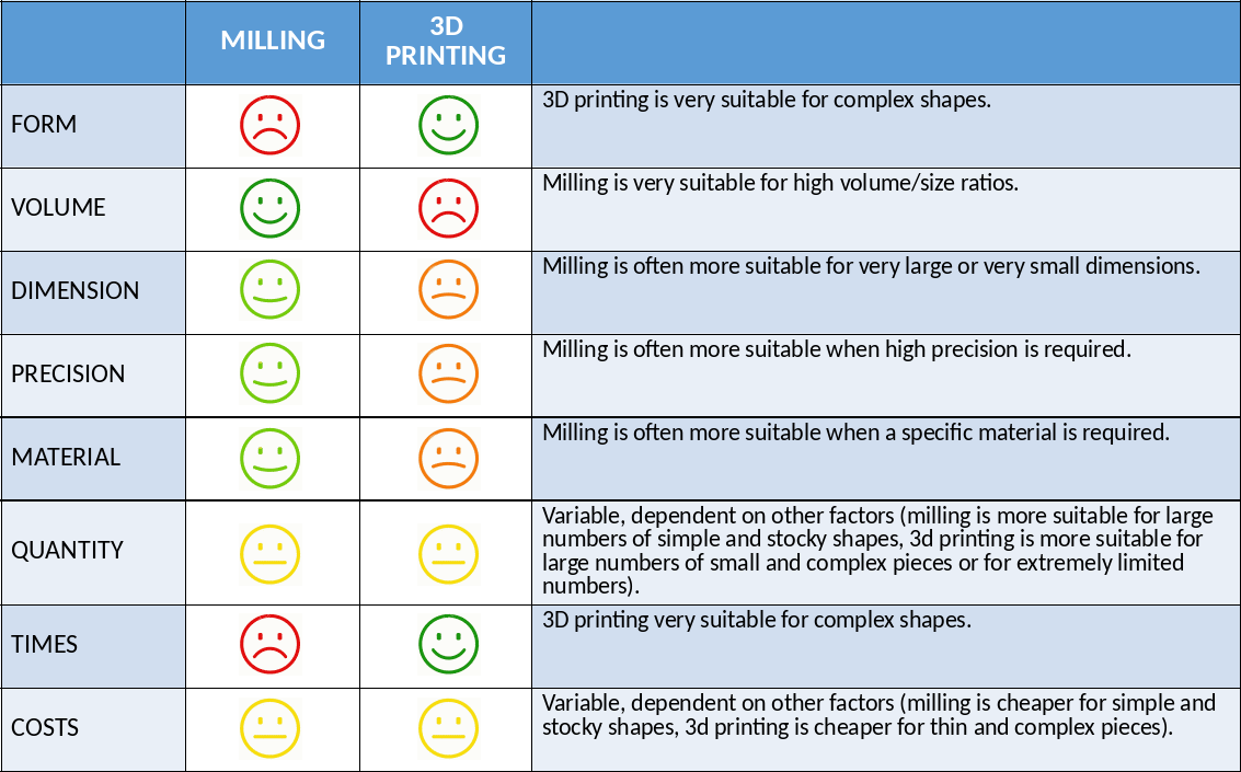
When considering other factors, such as size, precision, quantity and costs, the choice is more complex, the interactions between different factors must be analyzed and the specific characteristics of the different production technologies available in the two areas must be compared.
For easy reference on other media, this guide is also available in PDF format:
guide-milling-vs-3d-printing.pdf