Introduction
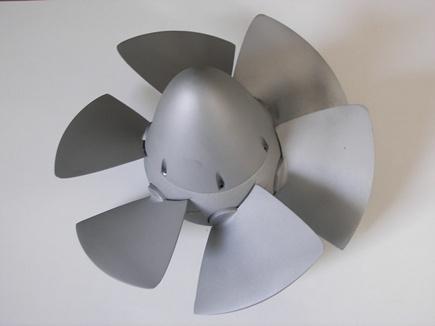
The problem faced in this research is the design and three-dimensional modeling of the impeller of a Kaplan hydraulic turbine. The study provides as a result the three-dimensional CAD model of the turbine to be used for subsequent refinements by means of finite element codes or directly for the production of the real impeller. Another important aspect concerns the study of the operation of the turbine outside project conditions, i.e. with different flow rates.
The idea of this work arises from the growing interest in clean and renewable energy sources, with particular reference to the hydroelectric sector where the margins for further development are mainly related to small plants (mini-hydro). Smaller plants are more versatile and have no negative effects on the environment. Moreover, the value of hydroelectric power plants distributed in the territory is not so much connected to the energy contribution that they can give to the national electricity demand, but rather in the possibility of using local water resources.
However, these systems have the disadvantage of developing limited power, with the consequent need to minimize design, installation and maintenance costs in order to make them economically profitable. In this context, the development of a system that allows the automation of some design phases can undoubtedly be an advantage; on the other hand, this instrument must bring a real benefit to the designer, leaving him the complete freedom in the design choices and by automatically executing only the "compulsory" of vane calculation and design.
Method
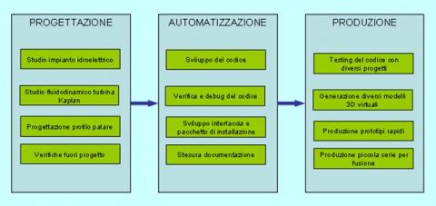
The first step in this research consisted in the study of the characteristics of a hydroelectric plant as a whole, in the analysis of the various parameters that allow to choose the machine to be installed, in the study of the method by which the machine diagrams of machine performance estimation at different operating conditions are plotted. Then our attention has been focused on the Kaplan turbine and on the theories that are used for its sizing and design.
Specifically, for the design of the impeller blades, we started from the nominal design conditions and analyzed the fluid-dynamic and the mechanical issues, and from these we derived the geometry of the blades, i.e. the shape and the thickness, related to the resistance of the blades to the strain. So you went to the analysis of the operation in out-of-project conditions. Finally, a process for modeling the impeller blade has been developed, including the generation of profiles by calculating the points in Visual Basic and exporting them to a CAD modeler where the solid model is built automatically.
Finally, some turbine prototypes were made using the models thus developed. The prototypes were realized on a real scale and on a scale of 1: 2 with the techniques of stereolithography and vacuum casting that allow to directly produce models drawn in the 3D CAD software.
Results
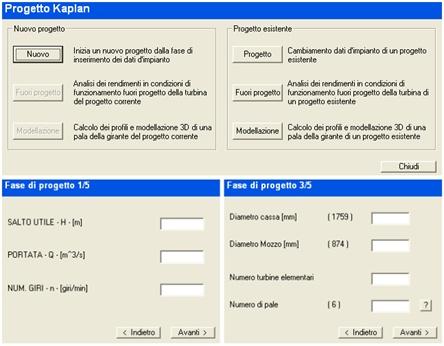
The result of this work is a code where the designer enters project data and his own technical assumptions. The calculation program then generates the profiles at various radius and places them on the corresponding circumference. These profiles, represented by a sequence of points, are saved in a file. The sequence of points is then added with appropriate instructions that allow you to drive a specific CAD modeler. In our case, the code generates a command list for Rhinoceros or for SolidWorks.
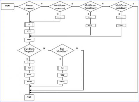
The code has been constructed in such a way that the designer can resume a project already made and modify it, or, within the same project, he can study the non-nominal conditions in different ways, or may otherwise proceed in the blade modeling stage.
In this way, the designer can actually concentrate himself on the highest level issues and experience a larger number of solutions, imposing different operating conditions and different technical assumptions without losing too much time in the computing and graphics processing details that can be automated.
Additional info
This research was carried out between April 2006 and March 2007, also thanks to the collaboration with a graduate of the University of Udine. The project was partially funded by the Friuli Venezia Giulia Region, by Law 47/78.
If you are interested in receiving more information, please use the contact form.


